

Overview
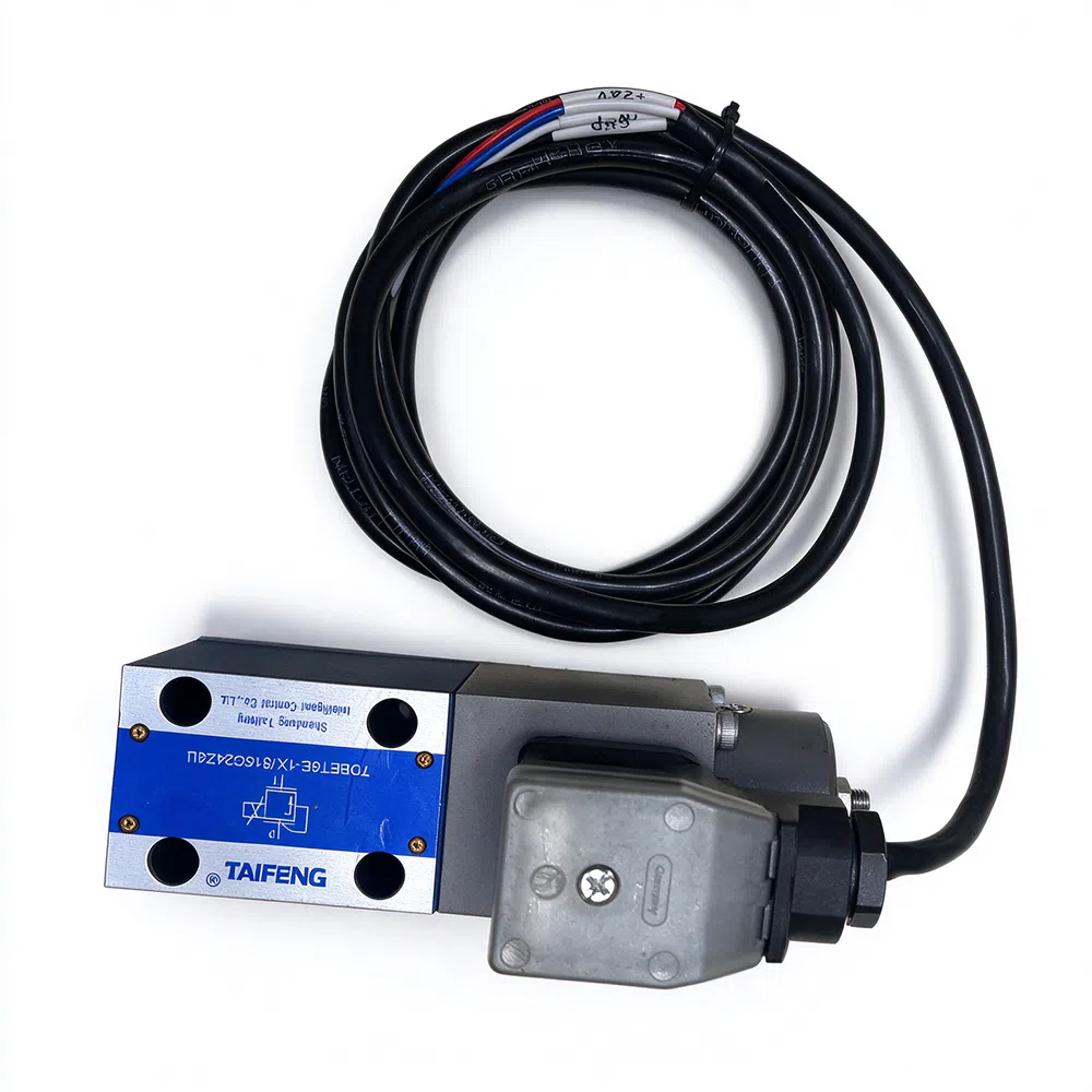
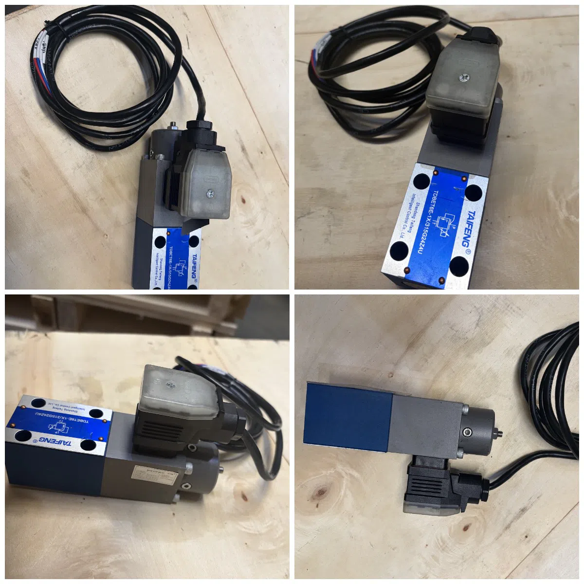
TDBET6E proportional relief valve controls the cracking pressure by a proportional solenoid that directly drives the cone spool. As the input current changes, the cracking pressure changes as well and is approximately proportional to the input current. This kind of proportional relief valve can be used in small flow hydraulic system, or as a pilot stage of pilot operated relief valve to limit the system pressure. It uses integrated digital proportional amplifier, which is controlled by open-loop control. The input command signal can be 0-10V voltage signal or 4-20mA current signal.
Working Principle
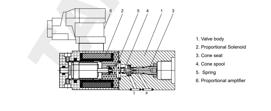
The valve is composed of valve body 1, proportional solenoid 2, cone seat 3, cone spool 4, spring 5, and proportional amplifier 6. The drive current is supplied to the proportional solenoid 2 through proportional amplifier 6, and the proportional solenoid 2 generates corresponding thrust, which push the cone spool 4 to act on the orifice of the cone seat 3. If the hydraulic force acting on the cone spool 4 is greater than electromagnetic force, the cone spool 4 is pushed away from the cone seat 3, and the pressure medium flows in from port p, and returns to the tank through port T, thereby limiting the system pressure no more than hope value. The system pressure can be adjusted by setting the command signal size to obtain corresponding driven current. In the case of zero input, the valve opening pressure is the lowest, and the system will obtain the minimum regulated pressure.
Basic Structure Cutaway View
Order Code
TDBET6E Proportional Relief Valve, Direct Operated

1. Basic Model TDBET6- NG 6 proportional relief valve
2. Electric Controller E - With integrated digital proportional amplifier
3. Control Form No code – open loop control
4. Design Series 1X - from 10 to 19, the installation and connection dimensions remain unchanged
5. Maximum Adjustment Pressure 50 - up to 50bar 100 - up to 100bar 200 - up to 200bar 315 - up to 315bar
6. Electric Controller Power Supply Voltage G24 - 24V DC
7. Electric Connection Plug Z4- With electrical connection seat to DIN 43650
8. Command Signal U- The input command input is 0 ~ +10 V I- The input command input is 4 ~ 20 mA
9. Seal Components Code No mark - NBR V - Viton
Electrical Connections
The terminals are pre-wired with 6 colors:
Red (Pin 1): power supply +24 V
Blue (Pin 2): Power supply 0 V
Yellow (Pin 3): reference output REF (+10 V)
White (Pin4): input signal IN+
Black (Pin 5): input signal IN-
Green(Pin 6): Monitoring signal MON (1 A=1 V)
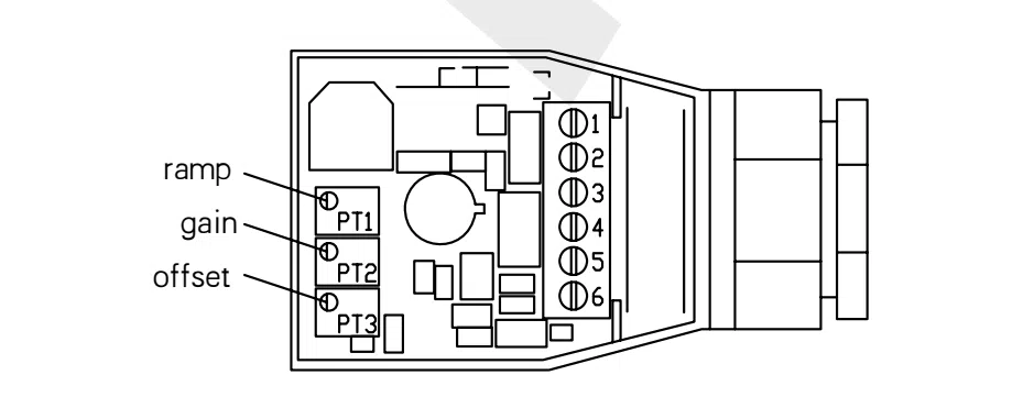
The amplifier internal structure diagram
Technical Parameter
| Parameter | Unit | Value |
|---|---|---|
| Storage temperature range | ℃ | -20 ... +80 |
| Working environment temperature range | ℃ | -20 ... +70 |
| Weight | Kg | 2 |
| Maximum working pressure (port P) | bar | 315 |
| Maximum regulation pressure | bar | 50, 100, 200, 315, same as pressure level |
| The regulation pressure when input valve is zero | bar | related to flow, see characteristic curve 3 |
| Return pressure (port T) | bar | separate return tank < 5 |
| Nominal flow | L/min | 1 |
| Working medium | mineral oil, phosphate hydraulic oil | |
| Working medium temperature range | ℃ | -20 ... +70 |
| Working medium viscosity | mm²/s | 15 to 380, 30 to 46 best |
Pollution degree The oil highest pollution degree according to NAS 1638 recommended filter minimum filter accuracy βₓ≥75 | Class 9, X=10 | |
Hysteresis The percentage of maximum regulated pressure | ≤ ±1.5 | |
Repeatability The percentage of maximum regulated pressure | ≤ ±2 | |
linearity The percentage of maximum regulated pressure | ≤ ±3.5 | |
Adjustment value deviation caused by system error The percentage of maximum regulated pressure | ±5% | |
| Step response time(0-100%) | ms | 30 to 150 |
| Installation location | any location |
Electrical parts
| Parameter | Unit | Value |
|---|---|---|
| Electric controller power supply voltage | DC 24 V(Minimum: 18 V, Maximum: 30 V) | |
| Working status | continuous | |
| Protection level | IP65 | |
| Solenoid electrical connection | Socket according to DIN 43650 | |
| Solenoid coil normal resistance | Ω | 20.3±5% at 20℃ |
| Solenoid rated current | A | 0.8 |
| Electrical controller signal - Voltage signal type | E503-A1H-U0/A1 | |
| Electrical controller signal - Current signal type | E503-A1H-I4/A1 |


