

Product Overview
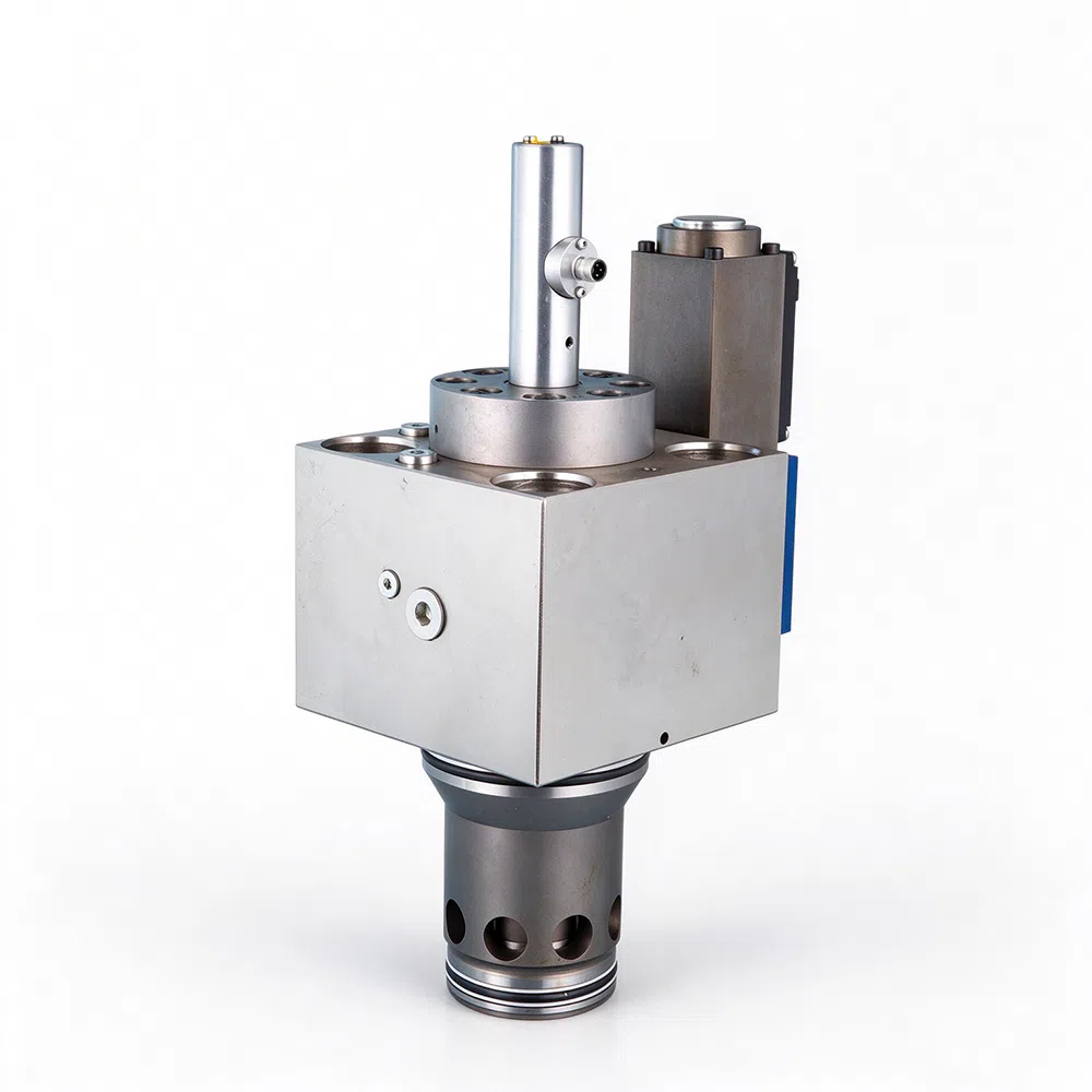
Our Dual‑Active Proportional Two‑Way Cartridge Valve** is high‑end poppet‑type screw‑in hydraulic logic element developed for modern high‑performance hydraulic systems Following ISO7368 / DIN24342 / GB2877 installation standards, this proportional cartridge valve delivers precise bi‑directional flow regulation under high‑pressure, large‑flow working conditions
As an upgraded variant of the standard two‑way cartridge valve, the dual‑active proportional cartridge adopts closed‑loop spool position feedback (LVDT), achieving accurate proportional throttling, fast response and low hysteresis. It is widely integrated into custom hydraulic manifold blocks, replacing traditional proportional spool valves for compact hydraulic power unit solutions in heavy‑duty industrial and mobile hydraulics.
Working Principle
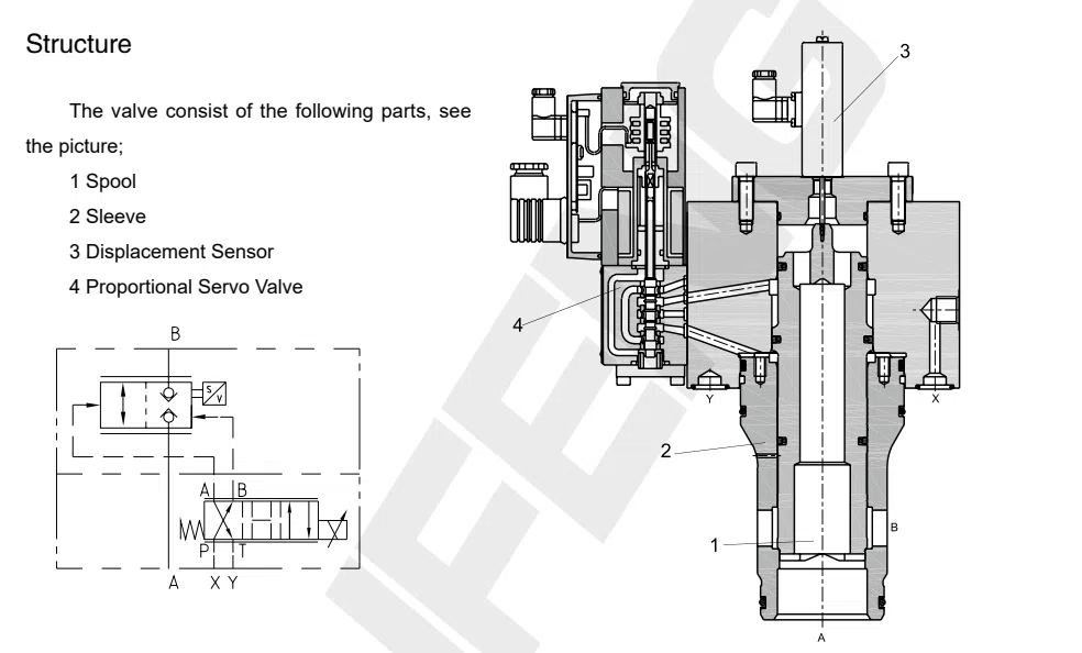
Control the flow according to the signal. Provide the suitable drive electricity to the proportional servo-valve through the amplifier to control the movement of the main spool. The dis placement sensor of the main spool feedback signal to calibrate the amount of valve opening, so that it can correspond to the amplifier input signal.
Model Description
Order Code of Dual Active Proportional Two-way Cartridge Valve

1.Cartridge Valve Code
TLCF - Multi-function cartridge valve
2.Nominal Diameter
Comply with ISO 7368 (DIN24342)
032 - NG 32 040 - NG 40 050 - NG 50 063 - NG 63 080 - NG 80 100 - NG 100
3.Function Symbols
Double active control
4.Spool Type
D - Control spool with control window
5. Design Series
1X - 10 to 19 series, connecting dimension no change.
6. Pilot Control Type
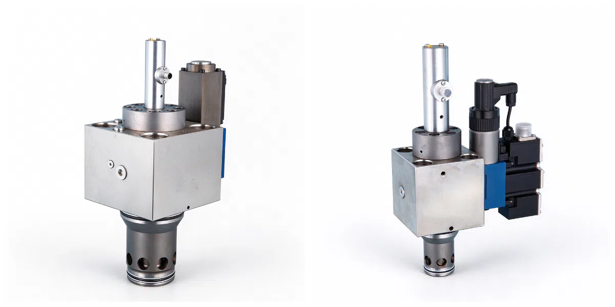
W - Pilot valve is solenoid valve S - Pilot valve is proportional valve with displacement sensor
7. Power Voltage
G24 - Power Supply Voltage +24VDC
8. Seal Component Material
No mark - NBR V - Viton
Technical parameter
Technical Parameter of Dual-Active Proportional Two-way Cartridge Valve
| Item | Condition / Symbol | Unit | 32 | 40 | 50 | 63 | 80 | 100 |
|---|---|---|---|---|---|---|---|---|
| Installation position | Optional | |||||||
| Environment temperature | ℃ | −20 ... +50 | ||||||
| Weight | NG | 32 | 40 | 50 | 63 | 80 | 100 | |
| Weight | kg | 9 | 15 | 25 | 50 | 110 | 180 | |
| Hydraulic Parts | ||||||||
| Working pressure | Pilot valve | bar | 10–315;Recommend 140–160 | |||||
| Working pressure | Main valve | bar | ≤350 | |||||
| NG | 32 | 40 | 50 | 63 | 80 | 100 | ||
| Fixed flow(main valve Δp=5bar) | L/min | 750 | 1100 | 1800 | 2800 | 4350 | 7200 | |
| Max. flow | L/min | 1450 | 2200 | 3500 | 5500 | 9000 | 14000 | |
| Nominal stroke | mm | 17.5 | 18 | 16 | 19 | 24 | 30 | |
| Control oil volume | cm³ | 4.52 | 8.48 | 18.5 | 36.3 | 67.9 | 132.5 | |
| Running time at pilot control pressure of 150bar | ms | 15 | 20 | 40 | 70 | 80 | 90 | |
| Hydraulic oil | Meet DIN51524 standard mineral oil(HL, HLP);phosphate(HFD-R) | |||||||
| Cleanliness level — Pilot stage | The highest oil contamination level comply with IS04406(C) class 18/16/13 | |||||||
| Cleanliness level — Main stage | The highest oil contamination level comply with IS04406(C) class 20/18/15 | |||||||
| Oil temperature range | ℃ | −20 ... +70 | ||||||
| Viscosity range | mm²/s | 20 to 380 | ||||||
| Hysteresis | % | ≤0.5 | ||||||
| Repeat accuracy | % | ≤0.2 | ||||||
| Response sensitivity | % | ≤0.2 | ||||||
| Electrical parts | ||||||||
| Line protection level comply with DIN 40050 | IP65 with fixed plug | |||||||
| Input voltage | DC | |||||||
| Signal form | Analog | |||||||
| Electronic amplifier | European plate, matching the valve |


