Product Overview
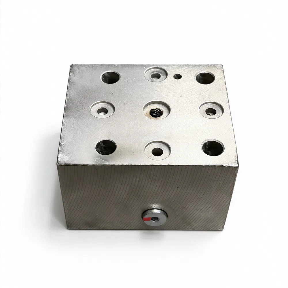
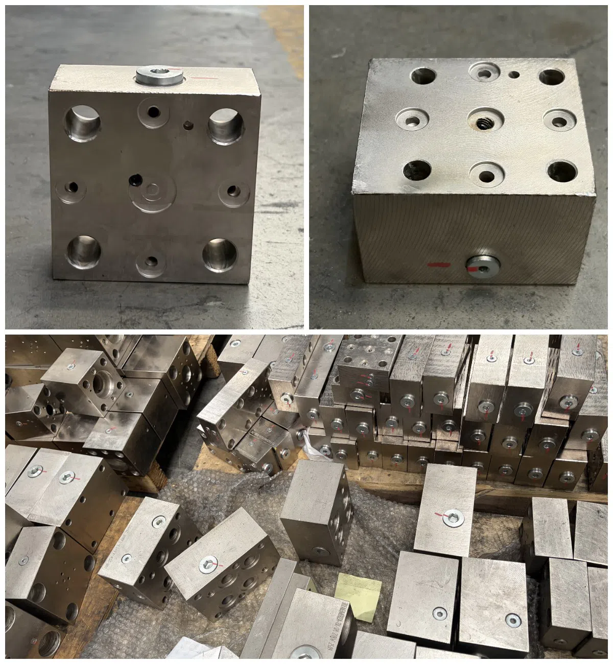
Our hydraulic manifold blocks (also known as valve blocks or integrated control blocks) are precision-machined components designed to consolidate complex hydraulic circuits into a single, compact unit. By integrating directional, pressure, and flow control valves into one solid block, we help you eliminate excessive piping, reduce leakage points, and significantly improve system response time.
As a specialized hydraulic valve block manufacturer, we support full customization—from single-piece prototypes to mass production—based on your specific circuit diagrams or 3D models.
Feature
New TLFA has the following characters
Innovative design in the TLFA series control covers is implemented. Screw-in cartridge valve is widely used in the embedded pilot control element, which makes the structure of control cover more reasonable, the use and maintenance more convenient. Available in various configurations.
You can choose cover plate of the universal plate connected solenoid directional valve and modular valve according to IS04401-03/05, or cover plate with screw in cartridge valve.
Generally, the control cover is chemically nickel- plated on the surface, so it has high corrosion resistance.
Model Description
Pressure Control Function Cartridge Order Code

1. Cover code
TLFA-Cartridge valve cover According to ISO7368
2. Nominal Diameter
According to ISO7368
(DIN24342)
016 - NG16 025 - NG25 032 - NG32 040 - NG40 050 - NG50 063 - NG63 080 - NG80 100 - NG100 125 - NG125 160 - NG160
Note: NG125, NG160 don’t comply with ISO/DIN, pls connecting Taifeng marketing dept when ordering.
3. Function Symbol
DB*– Relief valve DBR*– Check relief valve DBW*– Solenoid relief valve DBU – Solenoid relief valve DBZ – Two-stage pressure regulating relief valve
DBU2* – Two-stage pressure regulating solenoid relief valve
DBEM – Proportional relief valve DB – Reducing valve DBU– Proportional reducing valve DBWF– Solenoid reducing valve DZ– Sequence valve
Note: Solenoid valve must be separately ordered. Fastening screw is included in the list.
4. Design series
7X- MS Thread in bolt and pilot solenoid valve 6X- BS Thread in bolt and pilot solenoid valve
5. Plug and Orifice thread
None- MS Thread in end cap and damping orifice SM- SAE for plug, MS thread in damping orifice
SN- SAE for plug, NPT thread in damping orifice
6. Pressure range (bar)
025 - 3~25 050 - 5~50 100 - 10~100 200 - 120-200 315 - 160~315 350 - 180~350
7. Damping orifice size
No sign- Standard orifice size Standard damping orifice size of new product installation before leaving factory is in page
A-6, other size and position of damping orifice need be arranged by connecting with Taifeng marketing department.Nonstandard damping orifice
should specify its port layout and damping dimension.
8. Seal components
material No sign- NBR V- Viton
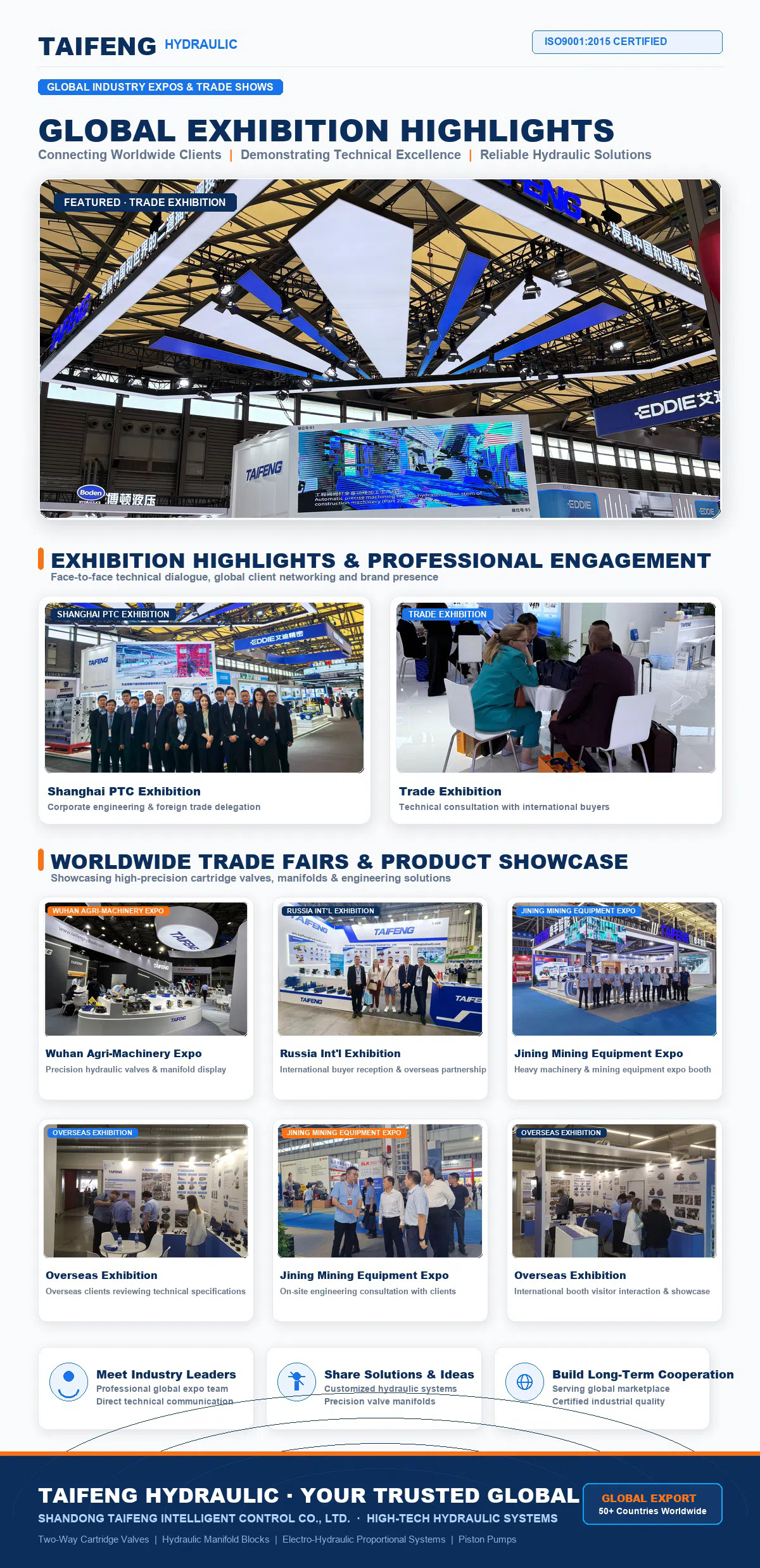
Trade Show
Taifeng Hydraulic on the World Stage: As a dedicated manufacturer of hydraulic systems committed to global expansion, we are consistently active on the international stage. By actively participating in major global industrial expos, Taifeng not only showcases high-precision hydraulic components but also builds deep trust and cooperation with clients worldwide. Scroll down to view our global exhibition highlights.